Services and Enterprise Canvas review – 4: Layers
What is a service-oriented architecture – particularly at a whole-of-enterprise scope? How best could we describe that architecture at different levels of abstraction, different levels of detail? If – as in many architecture frameworks – we could describe the architecture in terms of ‘layers’, what would those layers be? And what would be the content for each of those layers?
This is the fourth in a six-part series on reviewing services and the Enterprise Canvas model-type:
- Core: what a service-oriented architecture is and does
- Supplier and customer: modelling inbound and outbound service-relationships
- Guidance-services: keeping the service on-track to need and purpose
- Layers: how we partition service-descriptions
- Service-content: looking inside the service ‘black-box’
- Exchanges: what passes between services, and why
In the earlier parts of the series, we saw how each service needs support from a variety of other services, to guide and validate its actions, to coordinate its actions with other services and its changes over time, and support from various forms of investment and the like.
But how do we describe how to make all of this happen, or the back-and-forth of design and redesign? That’s where the idea of layers comes into the architectural picture. But what is a layer, in this architectural sense? How do we define them? More to the point, how do we use them?
Although there are many variations-upon-a-theme, in essence there are two basic approaches to layering that are currently in use in enterprise-architecture:
- layers as interrelated chunks of scope – as typified by the ‘BDAT stack’ (business, data, applications, [computer] technology) used in TOGAF, Archimate and the like
- layers as levels of abstract-to-realised – as typified by the ‘rows’ in the Zachman framework
Each approach is valid in its own way, but they’re not equivalent, and in some ways inherently incompatible with each other: don’t mix them up!
Most of the existing ‘enterprise’-architecture frameworks go for the first option: they select a set of chunks of scope – usually IT-centric, though sometimes more – and build a pattern of interrelationships between these chunks of scope, which are there described as ‘layers’. Which is fine enough if we’re only working with that specific set of scopes, and never need to touch anything beyond that collective scope. Which, however, is a very big ‘if’…
One of the fundamentals for a whole-of-context service-architecture – and hence for Enterprise Canvas – is that, by definition, we could be working with any scope at all. So ‘layer equals scope’ is often more of a hindrance than a help here – and sometimes a hugely misleading hindrance at that. In effect, for a service-architecture we need to view the architecture overall as a kind of hologram, where every description is a view into that holographic space, and where everything that we do in the architecture adds a bit more detail to the hologram which – because everything is ultimately interconnected with everything else – also inherently adds a little bit more detail to everywhere. Whether we like it or not, our scope in enterprise-architecture is always ‘the everything’: for simplicity’s sake, we can use the test of ‘Just Enough Detail‘ to limit our view somewhat, but it’s important to remember that that ‘the everything’ is always still there.
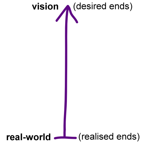
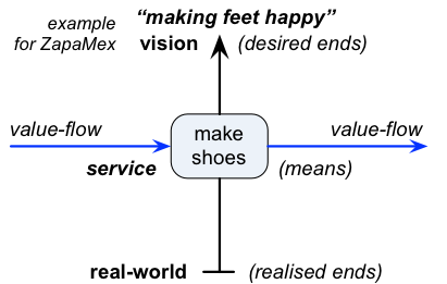
Which, in effect, pushes us towards that second option: layers as levels of ‘abstract-to-realised’. Probably the simplest way to visualise this is with that diagram about ‘the reason for doing anything’, that we met back near the end of the first post in this series:
The vision, up at the top, is the most abstract level of this tension: it itself is kind of fixed, but there’s always another way to reach towards it. The real-world, down at the bottom, is the most concrete or ‘realised’ level of this tension: it’s already happened, there’s nothing we can do any more to change it. Given this, it’s quite easy to imagine a suite of intermediate steps, or ‘levels’, between these two extremes, where descriptions are variously either more or less abstract, more or less concrete. As we go ‘up’ – and, incidentally, more toward the ‘why’ – the descriptions get more abstract, more replete with possibility for change; as we go ‘down’ – and more toward the ‘how’ and ‘with-what’ and suchlike – the descriptions get more concrete, more definite, more fixed.
All of these different types of architectural-descriptions will be needed, at various different stages, in order to enable the design, redesign and, perhaps most important, real-world implementation and use of an architecture. By moving up and down through the types of descriptions, we build a more complete picture of the overall ‘why’, ‘how’ and ‘with-what’ of the architecture, and of everything within it, all the way from big-picture intent to the most fine-grained detail.
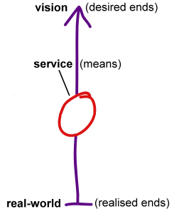
So, to services. As we saw in that post, a service represents a means via which we can reach towards the vision:
We’ve covered the basics of this in the previous posts. But if we now add in this idea of ‘levels of abstract-to-realised’, we can be more specific about what should be in each type of service-description – and also build descriptions that link between these ‘layers’, to build trails of provenance, requirements-trails, showing how each implementation and real-world entity realises the initial and overall intent.
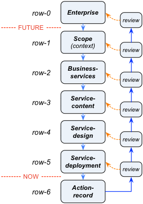
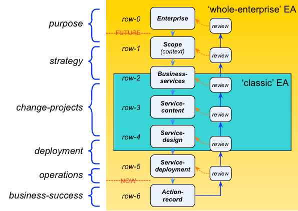
For Enterprise Canvas, we use an abstract-to-realised layering-model with seven discrete steps:
Each layer or ‘row’ downward adds something more to the description: for example, row-3 is implementation-independent, whilst row-4 is implementation-specific. The row-numbering starts at 0, rather than 1, for compatibility with the Zachman framework: rows 1-5 are approximately equivalent to the same row-numbers in Zachman.
- row-0, Enterprise: describes the shared-vision, values and core-principles to which the service should align – i.e. the ultimate anchor for its ‘vertical’ dimension
- row-1, Scope [current-Zachman: ‘Contextual’]: provides lists of key items that would be needed if the shared-enterprise is to be successful in reaching towards its shared-vision – i.e. the view includes abstract content needed so as to realise the vision
- row-2, Business-model [‘Conceptual’]: identifies roles and relations for and between the row-1 items – i.e. the service-view includes relationships between entities-as-services
- row-3, System-model [‘Logical’]: identifies more detail about the row-2 elements, and the interactions between them, but without specifying any form of implementation – i.e. the service-view includes ‘logical’-level detail
- row-4, Design-model [‘Physical’]: identifies the types of real-world entities needed to implement the ‘logical’-level model – i.e. the service-view includes ‘physical’-level detail
- row-5, Deployment-model (or ‘Operations/Action-plan’, as in the diagram above) [‘Detailed’]: identifies the instances of types of real-world entities needed to implement the ‘physical’-level model – i.e. the service-view includes full deployment/operations-plan detail
- row-6, Action-record: identifies what actually applied/was-used of the architecture at a given time (an ‘as-was’ view) – i.e. the service-view shifts to the non-changeable past
The key point about this type of layering is that it enables review of the architecture. Note too that whilst row-0 is, in principle, an unreachable ideal in the indefinable future, and rows 1-5 would all usually represent some form of future ‘to-be’, the transition between row-5 and row-6 represents the ‘travelling-Now’ – the moment at which the future becomes the present becomes the past. We can summarise that in visual form as follows:
(Remember again that layers in Enterprise Canvas are layers of abstraction within the same scope – and not arbitrary views into different parts of the scope, with arbitrary interconnections!)
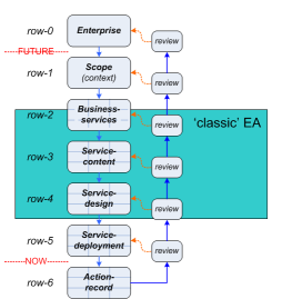
There’s also a useful distinction to draw here between the roles of a domain-architect – such as in the IT-specific orientation of TOGAF, or what we might call ‘classic’ EA – versus the whole-enterprise-architect and the solution-architect. The ‘classic EA’ touches into row-2, but doesn’t really go above that – that’d be classed as a business-strategist’s job, for example. They also don’t really go much below the middle of row-4 – which is where they cross over with and hand over to the solution-architect. The responsibilities of the ‘classic EA’ all sit pretty much in that middle range:
A whole-enterprise architecture, though, needs to cover the entire range of abstract-to-realised – all the way from row-0 to row-6 and back again:
The key responsibility-criterion, though, is that crucial phrase ‘Just Enough Detail‘. Going downward, the whole-enterprise EA-work needs to have very solid engagement in rows 0-3, with some cross-over with domain-architects from row-2 onward, and likewise an almost complete handover to the solution-architect by row-4. Yet on occasion, there’ll still need to be a deep-dive all the way down to the fine-detail of row-5 and row-6, wherever such detail might matter to a redesign-review further up. How to decide, though, which items of detail are the ones that matter, and that would justify a deep-dive? Short answer is that there’s no easy answer: the only real guide, in fact is the EA Mantra, that all enterprise-architects eventually learn for themselves – if often only the hard way…
Anyway, on to the specifics of service-descriptions for each of these layers or ‘rows’. I’ll use examples from a fictional company called ‘ZapaMex’ (Zapateros Mexicanos’ – ‘Shoemakers of Mexico’) to illustrate each of the layers:
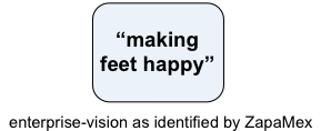
— Row-0 ‘Enterprise’ consists solely the shared-enterprise vision and (optional) values. For ZapaMex, the ultimate anchor for its quality and its service-architecture is the phrase “Making feet happy”:
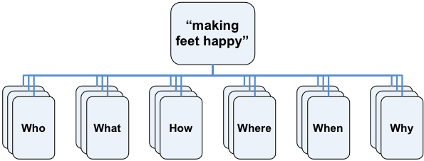
— Row-1 ‘Scope’ consists of simple lists, derived from the Zachman interrogatives, that describe entities needed to make the enterprise happen. For ZapaMex, I won’t list all of these entities here, but just show the interrogatives – who, what, how, where, when, why – from which the respective list would be derived:
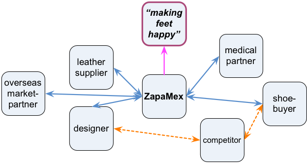
— Row-2 ‘Business Model’ is the first level at which we start to show the service itself, in context of other players in the enterprise:
Row-2 is also the first point at which we start to include relationships across the enterprise context-space. In this example, we map out various of the key players that ZapaMex would need to interact with, or need to consider in their business-model overview. Note that at this level we’re not particularly concerned with the details of the interactions and value-flows – more often just that the relationship exists, or needs to exist. As shown here, ZapaMex is one of various elements that would each aim to realise the shared-enterprise ‘Making feet happy’:
— Row-3 ‘System Model’ is where we start to add descriptive detail, much as per Parts 2 and 3 of this series. At this level, it’s still abstract, the so-called ‘Logical’ level: the moment we add specific implementation-detail – a specific technology or item or location or suchlike – we’d have jumped to row-4 (‘Physical’), and we need to be very careful about where and when and how much we’d do this kind of mixing of layers. (We’ll see more about this further below.)
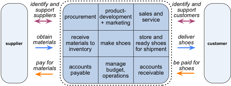
For ZapaMex, we might start off with an overly-simplistic row-3 – a point-to-point supply-chain, based on transactions only:
As we develop the model further, though, we’d need to describe more of the row-3 detail for service-delivery, including the ‘before-transaction’ and ‘after-transaction’ flows:
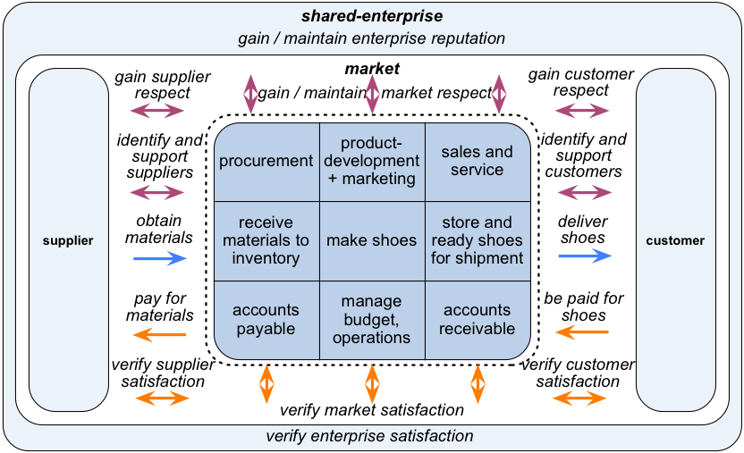
Eventually, we might well need to expand the row-3 modelling out to the full enterprise-context:
And also all of the interdependencies, relationships and flows for the guidance-services and investor/beneficiary relations, as described in Part 3 of this series:
The full checklist for all of that relationship-mapping is in the post ‘Enterprise Canvas as service-viability checklist‘; there’s also the ‘This’ game for service-oriented modelling with Enterprise Canvas and the like. And yes, if we really need to plot out everything for a given service, then true, it’d be a lot of work – a lot of work. But remember that guideline about ‘Just Enough Detail’: do only as much modelling as you really do need – no more than that, though also no less.
— Row-4 ‘Design Model’ is essentially the same as for row-3, except for one key difference: instead of specifying service-items in the abstract, we now fill in the real-world implementation-detail. For example, in the ‘receive materials to inventory’ service – ZapaMex’s instantiation of the generic ‘Supplier-Channels’ cell – we’d need here to spell out where that inventory-store is, what the services are that would handle the information about incoming materials and their storage-locations, how to pass on the supplier-invoices to the ‘accounts-payable’ service, and so on.
This tends to be more the realm of solution-architects rather than enterprise-architects – but the EAs certainly need to know how to get down to this level if need be.
— Row-5 ‘Deployment Model’ is, again, much like row-3 and row-4. The difference this time is that we’d add the next level of instantiation, the exact details of what is to be used, where and when. For example, in row-4 we might specify a specific model of server, a specific database-version, and so on; whereas here in row-5 we need to specify each respective computer’s serial-number, asset-number, IP-address and rack-location, and the exact instance-number and license-number for the database-package – the kind of information that would be in a real-time CMDB (Configuration-Management Database), a production-plan or a work-roster.
It’s true that even solution-architects wouldn’t usually go this deep, let alone enterprise-architects – it’s more the realm of system-administrators or production-managers or operations staff. Again, though, we do need to be able to do a deep-dive into this type of detail – particularly when hunting for items such as unrecorded and long-out-of-date business-applications that suddenly turn out to be business-critical when we try to shut them down!
— Row-6 ‘Action Record’ can be much the same as row-5, or even row-4: the key difference is that it’s all in the past, and therefore cannot be changed. It does tend to be simpler than row-4 or 5, though, if only because all of the future-oriented information has been stripped away. Much of the content at this level would be created automatically, as system-logs or transaction-records or models auto-generated from the CMDB – though some, of course, would necessarily be gathered in the old-fashioned way, on paper forms and the like.
Again, the only reason for an enterprise-architect to go this deep would be to chase up a problem, or go hunting into the past for ideas about the future. But yes, ‘Just Enough Detail’ means that sometimes we do indeed need to go this far down – so we need to know how to be able to find these records if and when we’d need them.
One other key concern about layering: a crucial distinction between composition and realisation. This is described in some detail in the post on ‘Simplifying the Enterprise Canvas‘ – a simplified notation, based on UML entity-modelling – with further detail in another follow-on post on the notation.
A composition-relationship between services, or service-descriptions, exists where one forms part of another, or an expansion of detail about another, within the same layer. In the simplified notation – in common with UML – we’d show this type of relationship with a diamond-headed arrow, with the arrow-head pointing to the larger-scoped service:
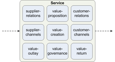
For example, we might say that a particular named type of machine (row-4) is made up of specific named assemblies (also row-4), or a named type of application has a specific type of front-end, middleware and back-end. Or, to give another example, the main delivery-service in Enterprise Canvas (row-3) is made up of, or composed of, the nine cells shown in that three-by-three matrix of inbound / self / outbound and before / during / after – and any or all of those nine cells may in turn be composed of other subsidiary services, all of them still described in abstract terms, and hence row-3.
(Archimate and UML both describe several different same-level relationship-types, including composition and aggregation. For our purposes here, composition alone should be sufficient: if you need the further detail, switch over to the respective other notation.)
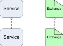
By contrast, a realisation-relationship between services, or service-descriptions, exists where one realises the other, at another layer. In the simplified notation – in common with UML – we’d show this relationship as an open-headed arrow, with the arrow-head pointing to the more-abstract (higher-row) service:
For example, we might say that an abstract-service such as ‘Make Shoes’, the Value-Creation cell for ZapaMex (row-3), is to be realised by specific machinery-types such as EUHT Heel and Sole Edge Trimming Machine, EWS-4 Goodyear Welt Sewing Machine, and ESS 828 Goodyear Sole Stitching Machine (row-4), which we then might even model down to the realisation of those machines themselves in terms of specific serial-numbers or factory-floor locations (row-5). Each of those relationships would be shown by a realisation-arrow.
In general, the open-arrow realisation-notation should be sufficient for most cases where we need to show service-descriptions from different layers on the same diagram. Sometimes, though, we’d want to show a composition-type relation by a ‘container’ type of notation:
Which works fine, until we also need to show a realisation-relation within the same container – otherwise known as mixed-layering. For this, we’d typically keep the solid-line borders for the service-descriptions in the main layer of interest, and dashed-line borders for service-descriptions in another layer. In the example below, about an e-commerce supply-chain, the main interest is about design for implementation (row-4), but with implementations for some items still not yet defined (i.e. still row-3) – so we use solid-line borders for the defined items, and dashed-line borders for the undefined items and the containing abstract-services:
(The dashed line with a solid-head arrow in the diagrams above represents a flow-relation – much as in UML. By convention, these would usually be shown as horizontal lines, to match up with the ‘horizontal’ flow of service-delivery in Enterprise Canvas. Also by convention, realisation-relations are usually shown as vertical lines, and with the upper-row entities above lower-row entities, to match up with the ‘vertical’ emphasis of that tension between vision and realised-ends.)
That’s probably enough on this for now – we’ll move on to explore how to describe service-content in the next part of this series.
Any comments or questions in the meantime, though? If so, over to you… 🙂





0 Comments on “Services and Enterprise Canvas review – 4: Layers”